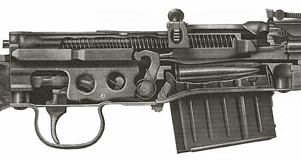
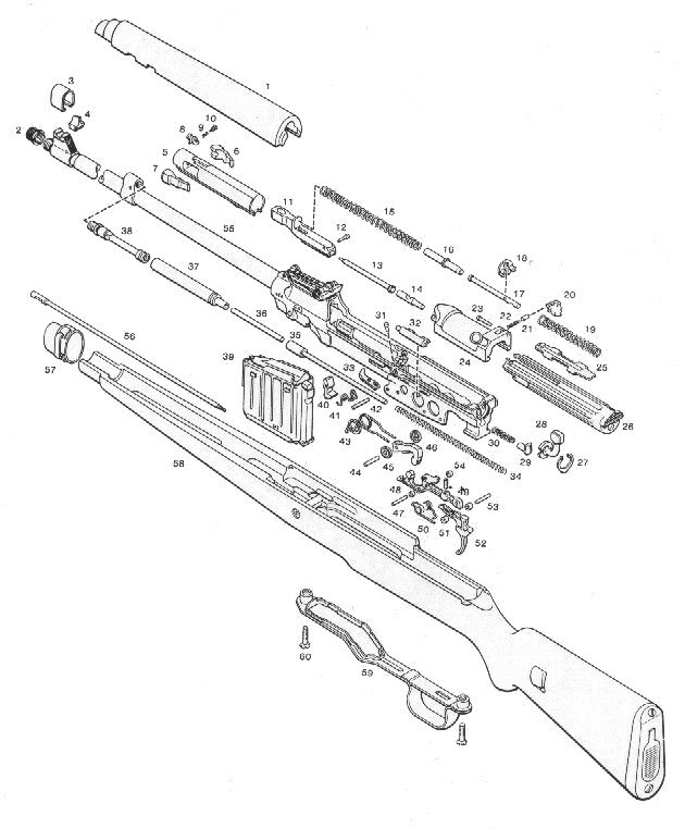
Exploded view of G/K43 + a technical advice
| At the end it"s indicated if a Serial Number (S/N = complete number, s/n = two digits) or a WaA was used on the part (not consistently) |
|
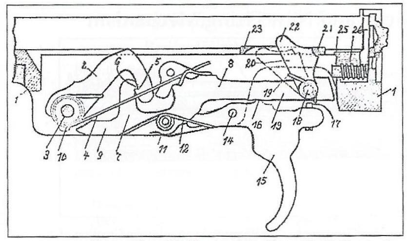
# 1: Handguard (Handschutz) # 2: Muzzle nut (Laufmutter) # 3: Sight hood (Kornschutz) # 4: Foresight (Korn) # 5: Bolt, stripped (Kammer) S/N WaA Bolt, complete (Schloß, Verschluß) # 6: Right locking lug (Stützklappe, rechte) s/n WaA # 7: Left locking lug (Stützklappe, linke) s/n WaA # 8: Extractor (Auszieher) s/n # 9: Extractor retainer (Auszieherbolzen) # 10: Extractor spring (Auszieherfeder) # 11: Firing pin housing (Verschlußstück, Schlagbolzensteuerstück) S/N WaA # 12: Retainer for firing pin extention (Bolzen zur Begrenzung) # 13: Firing pin (Schlagbolzen) WaA early ac # 14: Firing pin extention (Schlagstück) # 15: Recoil spring front (Schließfeder, vorne) # 16: Recoil spring guide, front (Führungsrohr) # 17: Recoil spring guide, rear (Führungsbolzen) # 18: Bolt housing retainer (Sperrscheibe für Schloßhülse, Schloßgehaüse) # 19: Recoil spring, rear (Schließfeder, hinten) # 20: Bolt hold open (Deckelsperre) # 21: Bolt hold open splint (Knoten für Deckelsperre) # 22: Bolt hold open spring (Feder für Deckelsperre) # 23: Bolt hold open pin (Stift für Deckelsperre) # 24: Bolt carrier (Verschlußdeckel) S/N WaA # 25: Sliding dust cover (Schutzshieber) # 26: Bolt housing (Schloßhülse, Schloßgehäuse) S/N WaA # 27: Safety retainer (Federring für Sicherung) # 28: Safety lever (Sicherungshebel) WaA early # 29: Safety plunger (S. Arrettierungsbolzen) # 30: Safety spring (Feder für Arrettierungsbolzen) # 31: Ejector pin (Bolzen für Auswerfer) # 32: Ejector spring with housing (Feder und Gehäuse für Auswerfer) # 33: Ejector (Auswerfer) # 34: Actuator rod spring (Feder für Stoßgestänge) # 35: Actuator rod (Stoßgestänge) WaA early # 36: Connecting rod (Verbindungsstange) # 37: Gas cylinder (Gaskolbenbuchse) S/N # 38: Gas piston (Gaskolben) WaA # 39: Magazine (Magazin) WaA Magazine housing (Magazingehäuse) WaA Magazine guide (Zubringer) Magazine spring (Zubringerfeder) Magazine floorplate (Magazinboden) # 40: Magazine catch (Magazinhalter) WaA # 41: Magazine catch spring (Feder für Magazinhalter) # 42: Magazine catch pin (Bolzen für Magazinhalter) # 43: Hammer spring (Schlagfeder) # 44: Hammer pin (Hammerhaltebolzen) # 45: Hammer washers (Distanzrollen) # 46: Hammer (Hammer) WaA # 47: Sear pin (Abzugsstangenbolzen) # 48: Sear spacers (Distanzrollen) # 49: Sear (Abzugsstange) # 50: Sear spring, trigger spring (Abzugsfeder) # 51: Trigger spacers (Distanzrollen) # 52: Trigger (Abzug) WaA # 53: Trigger pin (Haltebolzen für Abzug) # 54: Trigger adj. screw (Eichungsschraube für Abzug) # 55: Barrel (Lauf) WaA Receiver (Systemgehäuse) S/N WaA # 56: Cleaning rod (Putzstock) # 57: Front band (Oberring, Riemenbügel) Front band spring (Oberringhaltefeder) # 58: Stock (Schaft) S/N WaA (not late ac 45) Crosslug (Zapfenlager) # 59: Triggerguard (Abzugsbügel) # 60: Triggerguard screw (Systemhalteschraube) Front sight base (Kornsockel) WaA Gas cylinder sleeve (Gaskolbenhalter) WaA Gas cylinder sleeve pin (Stift für Gaskolbenhalter) Rear sight ramp (Visierkurvenschiene) Rear sight leaf + slide (Visierklappe + Schieber) WaA Rear sight spring (Visierfeder) Buttplate with trapdoor (Kolbenkappe) Bolt catch - activated by the magazine (Kammerfang) |
| Disassembly and assembly of the G/K43 |
|
Make sure the rifle is unloaded and safety in the
safe position (facing up or right hand side). Remove the
magazine from the rifle by depressing the magazine catch button
and pulling down and forward on the magazine. Remove cleaning
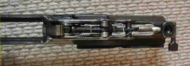
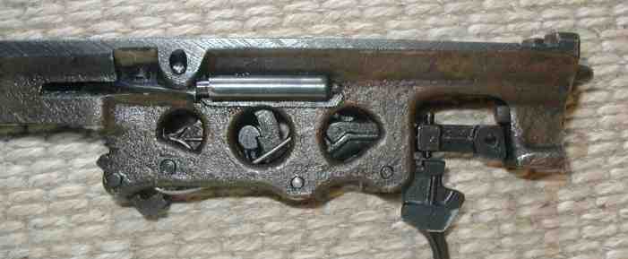
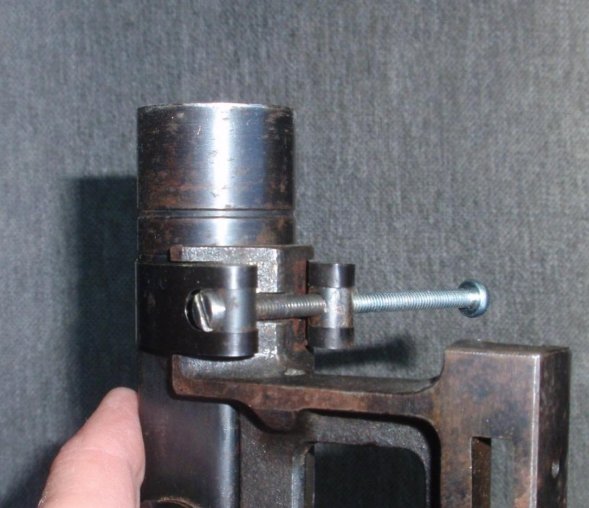
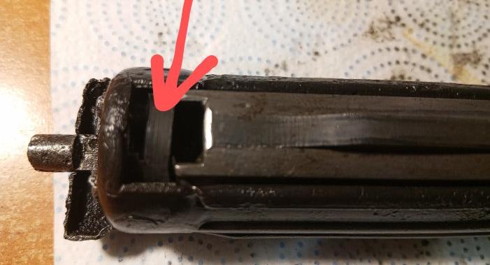
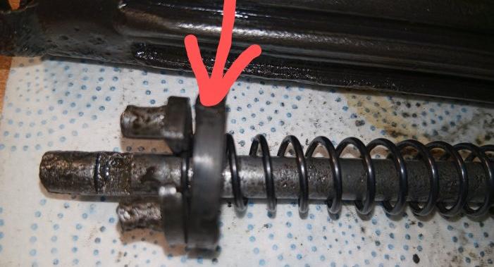
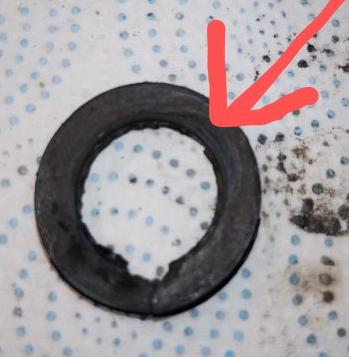
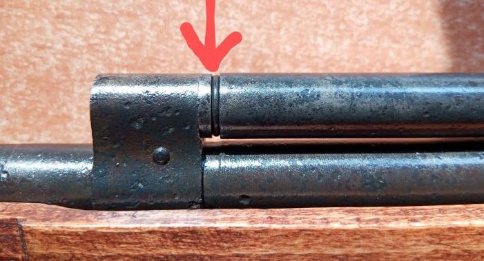
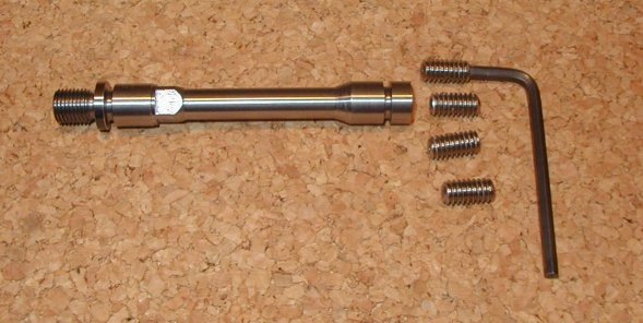
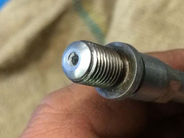
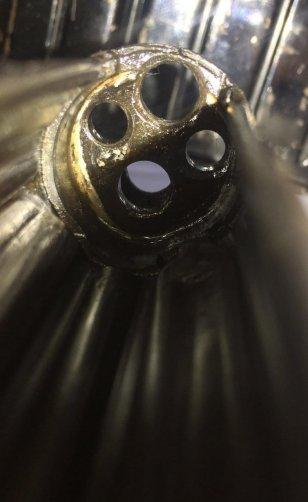
rod if present. If the rifle has a sling loosen it up a few inches. Now depress the front band spring, and slide the front band forward. You will now be able to remove the handguard. Pull back on the charging handle all the way to the rear, turn the safety lever to the right side and depress the hold open lever on the right side of the bolt carrier. At the rear of the receiver is a button (just above the safety) depress the button, and the bolt assembly will pull upwards and out of the receiver starting with the rear part of the bolt assembly. *Note: if you have a late Walther gun, there may not be a hold open catch. Pull the bolt assembly to the rear, and depress the takedown button, but beware! the parts are under spring tension, and will fly everywhere if you do not keep both hands firmly on them, and always protect your face! Now with the bolt in both hands cupped firmly, depress the hold open catch. The recoil springs will push the bolt open and you can now easily disassemble everything by hand. The recoil guide assembly and rear recoil spring can be easily disassembled, or cleaned and oiled as a unit. Turn the rifle over. There are two screws which hold the trigger guard in place. They have four notches in them that catch spring loaded pressure pins in the trigger guard. Depress the pins with a small punch while loosening the screws. Once you have removed the screws, pull forward on the magazine catch to release the trigger guard. Now the stock will slide off of the action. To remove operating rod components: Push the actuator rod rearwards to give clearance to remove the small connecting rod. Now slide the actuator rod and spring forwards and outwards. The gas cylinder can now slide rearward and off. The gas piston can be removed with a small crescent wrench. I would not recommend further disassembly of front or rear sights and trigger assembly unless absolutely necessary to remove broken or otherwise unusable parts. Cleaning and oiling of these parts can be done in place. Once you have cleaned and oiled the parts: Insert the firing pin into the firing pin housing. (long semi rectangular shaped piece). Insert firing pin extension (small tapered rod with a notch in the thinner area) fat end first into the firing pin housing. (note: there is a small retaining pin in the rear of the firing pin housing that seats in the firing pin extension recess) Insert the complete firing pin assembly into the bolt. Bolt will have elliptical cut out in front facing up, as will firing pin housing. Insert left and right locking flaps into bolt (this may take some practice to get right) and slide firing pin extension all the way in. Note: locking flaps are not reversible. the right side flap has a groove on the bottom which corresponds to a bulge in the right side lug bolt channel Insert long recoil spring into rear of bolt, seated on top of firing pin extension. Insert complete rear (small) recoil spring assembly into stamped sheet-metal bolt housing so that take down pin pokes out the top rear hole and other two pins poke out the side rear holes. Insert bolt carrier (handle) foot at the front into the elliptical cutout in the bolt making sure it seats also in the elliptical cutout in the firing pin extension. Now slide the front recoil spring onto the rod assembly that is holding the rear recoil spring in the stamped housing. You will begin to experience tension. Align the bolt carrier to slide back over the recesses for it in the stamped housing. Continue to pull it back under tension as far as it will go- to the rear of the housing. Now, with the assembly all the way back, engage the hold open catch on the rear of the bolt. This should hold everything into place. Making sure the safety is turned to the right (the hammer must be cocked first), slide the bolt assembly front end first into the receiver until it "seats itself." simply depress the takedown button, and it will drop the rest of the way in and lock. Now reassemble the rest of the rifle in the exact reverse order of disassembly. (Credits to K98k Mauser Page) If you have a "no hold open bolt": Taking such a bolt out is kind of easy. All you have to do is press the button, pull the bolt back a tiny little bit, then lift the housing out. And installing it did indeed take a while as there is just a tiny little sweet spot you have to hit to get it to drop down. How to mount the safety lever See the picture below. Use snap ring pliers. The tap has to point downwards. It's a good idea to turn the trigger-guard screw fully up so it hits the safety-plunger and then takes the pressure from the safety-plunger spring. 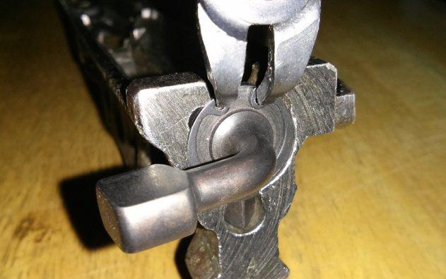 A "crack" in the bolt housing ? Many G/K43 rifles exhibit this "crack" in the bolt housing, some more, some less pronounced. The "crack" is not actually not a crack. The bolt housing is made from sheet metal, much like rolling a cigarette (or a joint, if you're from California or Colorado). The back end is then folded over and a cup shaped reinforcement welded against it from the inside. The "crack" is where the folded parts overlap. The hole near the "crack" has no supporting function at all. The bolt housing is held in place by two pins poking through the holes at center line. The hole near the crack is only there to allow the firing pin extension to pass through while cycling. 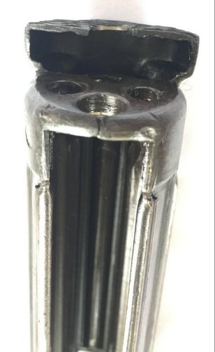
|